

![]()
This document is intended to acquaint Florida's general public with typical methods of heating household water by means of the sun. The types of solar systems discussed are pumped (both direct and indirect), thermosiphon and integral collector storage.
The following solar water heating systems are described:
Direct Pumped Systems
Differential controller operated system
Photovoltaic operated system
Indirect Pumped System
Drain Back System
Integral Collector Storage (ICS) System
Thermosiphon System
For more information
Direct Pumped Systems
Differential controller operated system
The direct pumped system, illustrated in Figure 1, has one or more solar energy collectors installed on the roof and a storage tank somewhere below, usually in a garage or utility room. A pump circulates the water from the tank up to the collector and back again. This is called a direct (or open loop) system because the sun's heat is transferred directly to the potable water circulating through the collector tubing and storage tank; no anti-freeze solution or heat exchanger is involved.
This system has a differential controller that senses temperature differences between water leaving the solar collector and the coldest water in the storage tank. When the water in the collector is about 15-20° F warmer than the water in the tank, the pump is turned on by the controller. When the temperature difference drops to about 3-5° F, the pump is turned off.
In this way, the water always gains heat from the collector when the pump operates.
A flush-type freeze protection valve installed near the collector provides freeze protection. Whenever temperatures approach freezing, the valve opens to let warm water flow through the collector.
The collector should also allow for manual draining by closing the isolation valves (located above the storage tank) and opening the drain valves.
Automatic recirculation is another means of freeze protection. When the water in the collector reaches a temperature near freezing, the controller turns the pump on for a few minutes to warm the collector with water from the tank.
Figure 1. Typical direct pumped system
Photovoltaic operated system
The system shown in Figure 2 , differs from other direct pumped systems in that the energy to power the pump is provided by a photovoltaic (PV) panel. The PV panel converts sunlight into electricity, which in turn drives the direct current (dc) pump. In this way, water flows through the collector only when the sun is shining.
The dc pump and PV panel must be suitably matched to ensure proper performance. The pump starts when there is sufficient solar radiation available to heat the solar collector. It shuts off later in the day when the available solar energy diminishes. As in the previous systems, a thermally operated valve provides freeze protection.
Common appliance timers also may control solar system operation. These timers must incorporate battery backup in the event of power failures.
The timer is set to operate during a period of the day when solar radiation is available to heat the potable water. In order to avoid loss of energy from the tank during overcast days, the collector feed and return lines are both connected at the bottom of the storage tank with a special valve. During normal operation, natural stratification allows the warmer water to rise to the top of the tank.
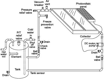
Figure 2. Direct system with photovoltaic-powered pump
Indirect Pumped System
This system design is common in northern climates, where freezing weather occurs more frequently. An antifreeze solution circulates through the collector, and a heat exchanger transfers the heat from the antifreeze solution to the tank water. When toxic heat exchange fluids are used, a double-walled exchanger is required. Generally, if the heat exchanger is installed in the storage tank, it should be in the lower half of the tank.
The system illustrated in Figure 3 is an example of this system type. Here a heat transfer solution is pumped through the collector in a closed loop. The loop includes the collector, connecting piping, the pump, an expansion tank and a heat exchanger. A heat exchanger coil in the lower half of the storage tank transfers heat from the heat transfer solution to the potable water in the solar storage tank. An alternative of this design is to wrap the heat exchanger around the tank. This keeps it from contact with potable water.
The brain of the system is a differential controller. In conjunction with collector and tank temperature sensors, the controller determines when the pump should be activated to direct the heat transfer fluid through the collector.
The fluid used in this system is a mixture of distilled water and antifreeze similar to that used in automobiles. This type of fluid freezes only at extremely low temperatures so the system is protected from damage caused by severe cold.
Figure 3. Indirect pumped system using antifreeze solution
Drain Back System
A fail-safe method of ensuring that collectors and collector loop piping never freeze is to remove all water from the collectors and piping when the system is not collecting heat. This is a major feature of the drain back system illustrated in Figure 4 (see page 3). Freeze protection is provided when the system is in the drain mode. Water in the collectors and exposed piping drains into the insulated drain-back reservoir tank each time the pump shuts off. A slight tilt of the collectors is required in order to allow complete drainage. A sight glass attached to the drain-back reservoir tank shows when the reservoir tank is full and the collector has been drained.
In this particular system, distilled water is recommended to be used as the collector loop fluid- transfer solution. Using distilled water increases the heat transfer characteristics and prevents possible mineral buildup of the transfer solution.
When the sun shines again, the pump is activated by a differential controller. Water is pumped from the reservoir to the collectors, allowing heat to be collected. The water stored in the reservoir tank circulates in a closed loop through the collectors and a heat exchanger at the bottom of the solar tank.
The heat exchanger transfers heat from the collector loop fluid to the potable water in the solar tank.
Figure 4. Indirect pumped system using distilled water
Integral Collector Storage (ICS) System
In the integral collector storage solar system shown in Figure 5, the hot water storage system is the collector. Cold water flows progressively through the collector where it is heated by the sun. Hot water is drawn from the top, which is the hottest, and replacement water flows into the bottom. This system is simple because pumps and controllers are not required. On demand, cold water from the house flows into the collector and hot water from the collector flows to a standard hot water auxiliary tank within the house.
A flush-type freeze protection valve is installed in the top plumbing near the collector. As temperatures near freezing, this valve opens to allow relatively warm water to flow through the collector to prevent freezing. In south Florida and certain areas of central Florida, the thermal mass of the large water volume within the ICS collector provides a means of freeze protection.
Figure 5. Integral collector storage system
Thermosiphon System
A typical thermosiphon system is indicated in Figure 6. As the sun shines on the collector, the water inside the collector flow-tubes is heated. As it heats, this water expands slightly and becomes lighter than the cold water in the solar storage tank mounted above the collector. Gravity then pulls heavier, cold water down from the tank and into the collector inlet. The cold water pushes the heated water through the collector outlet and into the top of the tank, thus heating the water in the tank.
A thermosiphon system requires neither pump nor controller. Cold water from the city water line flows directly to the tank on the roof. Solar heated water flows from the rooftop tank to the auxiliary tank installed at ground level whenever water is used within the residence.
This system features a thermally operated valve that protects the collector from freezing. It also includes isolation valves, which allow the solar system to be manually drained in case of freezing conditions, or to be bypassed completely.
Figure 6. Thermosiphon system
For more information
FSEC has other publications on solar heating of household water and swimming pools. A companion document entitled Solar Hot Water Q&A , (FSEC-EN-5), will address economics, installation, and sizing.
© 2007-2014 University of Central Florida. The Florida Solar Energy Center (FSEC)
is a research institute of the
University of Central Florida.
For more information about FSEC, please contact us or learn more about us.
Find us on Facebook!