

![]()
HVAC
Air Conditioning Equipment
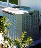 |
| Figure 20. HVAC Unit |
|---|
An important objective in selecting the cooling equipment for the PVRES home, was to take advantage of the features designed to reduce cooling loads. We used RHVAC (Elite Software) to calculate the cooling system size for both the standard home and the control home. RHVAC uses Manual J for its calculations. We entered the building features for either house in detail (walls, roof, glass, duct system etc.), but as a conservatism we chose an 95oF outdoor design temperature rather than the 91oF, suggested by Manual J, along with a 75oF interior temperature. The Manual J calculations indicated a cooling system of 3.88 tons for the standard home (4 tons) and 1.73 ton (2 tons) for the PVRES house.
Although, the two ton system for such a large home (2,425 square feet) is highly unusual, Ward's Air Conditioning in Lakeland and the Orlando and Tampa Trane offices worked with FSEC to come up with a suitable system. In a related project, we had a very good experience with Trane's XL 1400 series air conditioner [16]. Consequently, we selected the TWY024A two-ton heat pump for the project. We used the TWE040E13 variable speed indoor air handler to provide optimum efficiency, humidity removal and quiet operation. The Seasonal Energy Efficiency Ratio (SEER) of the combination is 14.4 Btu/W; the analogous Heating Season Performance Factor (HSPF) is 8.5 Btu/W. For the standard home we utilized the a standard efficiency 4-ton Trane heat pump which the project builder typically installs in his homes - a TWR048C (SEER = 10.0 Btu/W; HSPF = 7.0 Btu/W). The two units are shown in Figure 20; note the larger size of the condenser for the smaller, more efficient unit at the PVRES house.
Air Conditioner Performance Testing
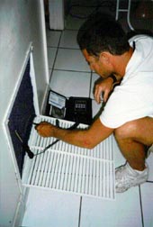 |
Figure 21. Digital Thermometer |
|---|
After each air conditioner was installed, we performed tests on April 8, 1998 to establish the relative performance of each. We developed a procedure entirely based on physical measurements, that can be used to measure the instantaneous efficiency of a cooling system. First the dry coil air flow is determined by turning on the heat pump back-up resistance heat elements and measuring the temperature rise across the heating coil. We used a portable Cooper Instrument Corp. SH66A multi-probe digital thermometer to do take this measurement (Figure 21). By simultaneously measuring the element wattage (we turned off all non-AC breakers and measured this using the utility meter), the air flow cfm can be gauged through knowledge of air's specific heat and density. As a check, we used a Shortridge flow hood to verify the estimate obtained by the resistance heat method (Figure 22).
Secondly, the air conditioner is set on to cooling and the temperature drop measured across the coil. Within the tests, we used two temperature probes before and after the coil. One set of the probes recorded the dry bulb temperature. The other two probes had water saturated cotton shoe-laces inserted into the air stream to measure the wet bulb temperatures before and after the coil. This would allow determination of the AC latent performance by looking at the change in enthalpy across the evaporator coil. As a check on this measurement, we also collected air conditioner condensate over a ten minute period once flow had begun. Finally, an outdoor temperature is taken at the condenser inlet since the rated EER of units is typically based on this condition and that indoors.
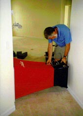 |
| Figure 22. Flow Hood |
|---|
The product of the change in enthalpy across the evaporator coil times the measured air flow yields the total cooling. By measuring the power demand of the AC system, the system energy efficiency ratio (EER) is obtained.
The measured air flow for the four ton heat pump at the Control house was 1,555 cfm or about 390 cfm/ton. This is well within the tolerance established for the air conditioner (400 cfm/ton). A 16.5 degree temperature drop was measured across the coil (Treturn = 69.2o; Tsupply = 52.7o; Treturn, wet = 59.4o; Tsupply, wet = 50.8o). The measured sensible cooling capacity of the unit at a 77.4o degree outdoor temperature was 26,680 Btu/hr; the latent cooling capacity was 8,560 Btu/hr for a total capacity of about 35,240 Btu/hr. With a 4,181 Watt power draw; this works out to an EER of 8.4 Btu/W. This is short the nominal SEER of 10 Btu/W, but the indoor temperature was much lower (69.2oF) than the 80o assumed in the ARI test procedure.
The test at the PVRES home was done with the variable speed air handler (VSAH) operating at full speed. The unit was configured with the VSAH operating much of the time it operates at less than half speed since measured on cycles last about six minutes.
© 2007-2014 University of Central Florida. The Florida Solar Energy Center (FSEC)
is a research institute of the
University of Central Florida.
For more information about FSEC, please contact us or learn more about us.
Find us on Facebook!